Aaron Laufs has very successfully implemented the outsourcing of a control system for winding systems to a programmable logic controller as part of his bachelor thesis. A winding model with dancer and tension control, which was equipped with system components from our premium system partner Mitsubishi Electric, is used to analyze and apply the developed software.
Motivation and background
In a previous bachelor thesis, we designed and implemented the model of the winding system with PLC-based control. The existing test model has now been modified and equipped with software and hardware from Mitsubishi Electric. “Together with Mitsubishi, I have developed a control basis for winding applications that can be used flexibly in the future for different motor and system sizes,” reports Aaron.
With this bachelor’s thesis, Aaron Laufs graduated summa cum laude from Aachen University of Applied Sciences in the field of automation and drive technology. After his apprenticeship and initial work experience, Aaron decided to study full-time, which led him to QA in the middle of last year. After his internship semester and his bachelor thesis at QA, Aaron will start his master studies in the coming semester. We would like to wish him every success and are already looking forward to an exciting master’s thesis.
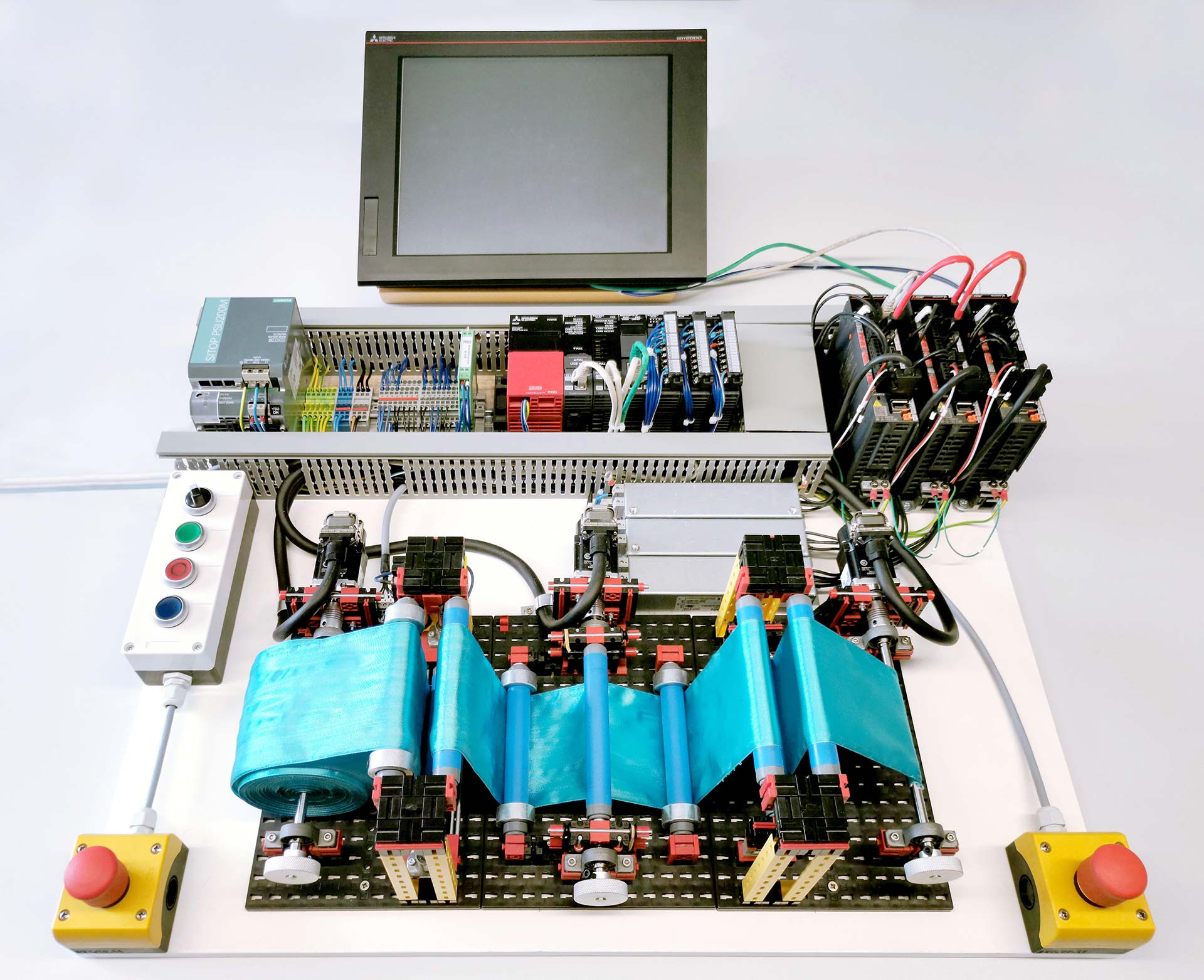
The test setup
The model made of Fischertechnik components simulates almost real conditions. A feed unit in the middle between the two winding units sets the speed. On the left side, a dancer control is implemented. In this process, the material is guided behind the winder via a vertically freely movable dancer. If possible, the dancer should always remain in a central position, and the control system reacts to deviations from this position. The path is measured by a sliding potentiometer. For the second method, tension control, a fixed deflection roller is used, with force sensors attached to its foundation. Here, the tension on the roller defines the controlled variable.
Process control and software design
The entire process control is carried out in the digital domain and thus poses certain challenges for a functioning control. The analog signal is first discretized with respect to the sampling time, which allows a snapshot at fixed time intervals. Subsequently, the conversion into a digital value takes place. Great demands are placed on data processing and transmission in particular, since synchronous processing of the data must be ensured within the digital control. This is the only way to ensure a time-continuous output of the manipulated variable.
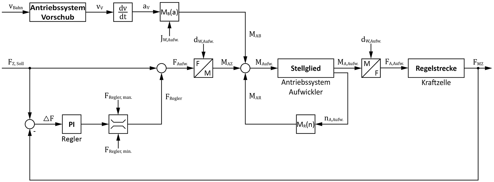
The dancer and tension control was implemented as feedforward control. On the one hand, this has the advantage that the controller is relieved, since only existing control deviations have to be compensated. On the other hand, the improvement of the dynamic behavior results in a faster reaction to changes in the reference variable or disturbance variable. In order to be able to use the feedforward control, all physical relationships within the application had to be determined. These included the winding diameter, the web speed, the tensile force and the torque. To map the physical processes, new function blocks had to be created that realize the calculation of the required variables. These include, for example, the diameter calculation of the windings, friction compensation and torque precontrol. The PI controller was realized with a Mitsubishi module.
Results and further application areas
The tension control has a very good control behavior, the reference variable is reached after about one second. The accuracy of the command behavior is ±(13.9 ± 8.66) mN (max. control deviation ± accuracy of measuring system). The dancer control has an accuracy of ± 3.2 mm. It should be noted here that the dancer is an inert system, so that changes in the manipulated variable can only be detected in the system with a delay. The good control behavior ensures that disturbance variables are quickly compensated for. In particular, tension control ensures high accuracy of the tension force and should accordingly be used for such applications.
With regard to PLC-based control, the developed application offers a wide range of application areas. However, the latency of the bus system and the PLC in relation to the required process must always be taken into account here.
Furthermore, the developed function blocks can also be used on other control platforms, which is made possible by the open source programming. The development of the essential function blocks for the application was realized independent of the man
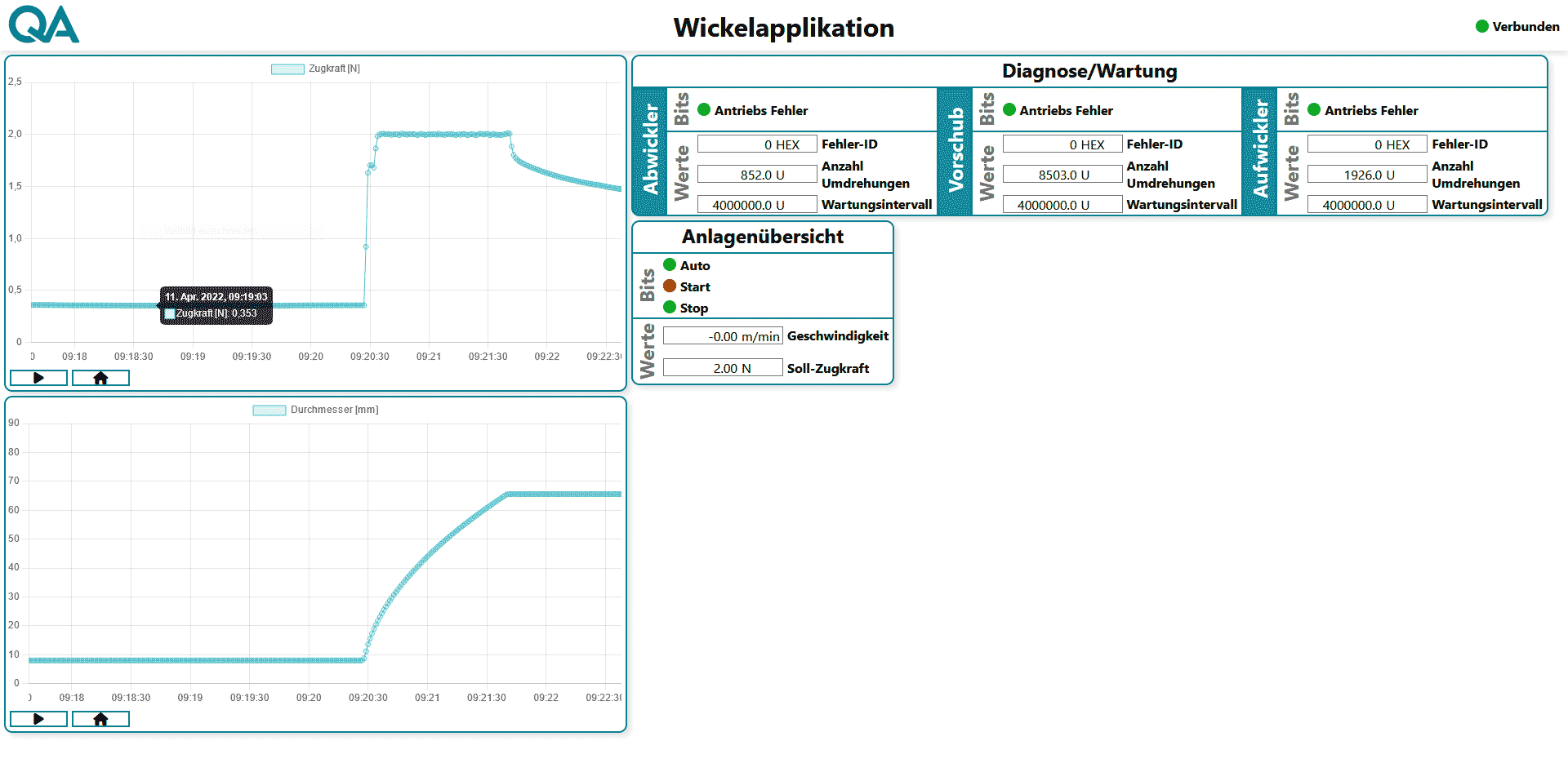
Process data monitoring through MQTT connection
By implementing an MQTT card, process data monitoring via web interface was created using Mosquitto as MQTT server. On a website programmed with HTML, CSS and JavaScript, among other things, the tensile force, the diameter and the plant status can be monitored.