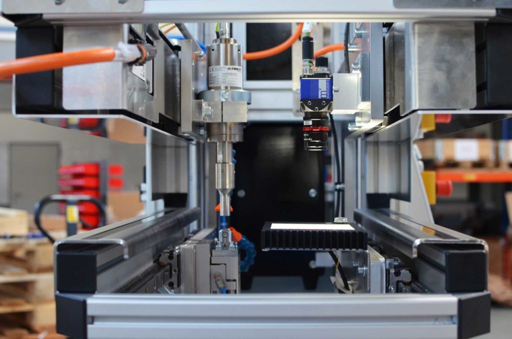
Ultrasonic Cutting Machine, Ultrasonic head and camera system
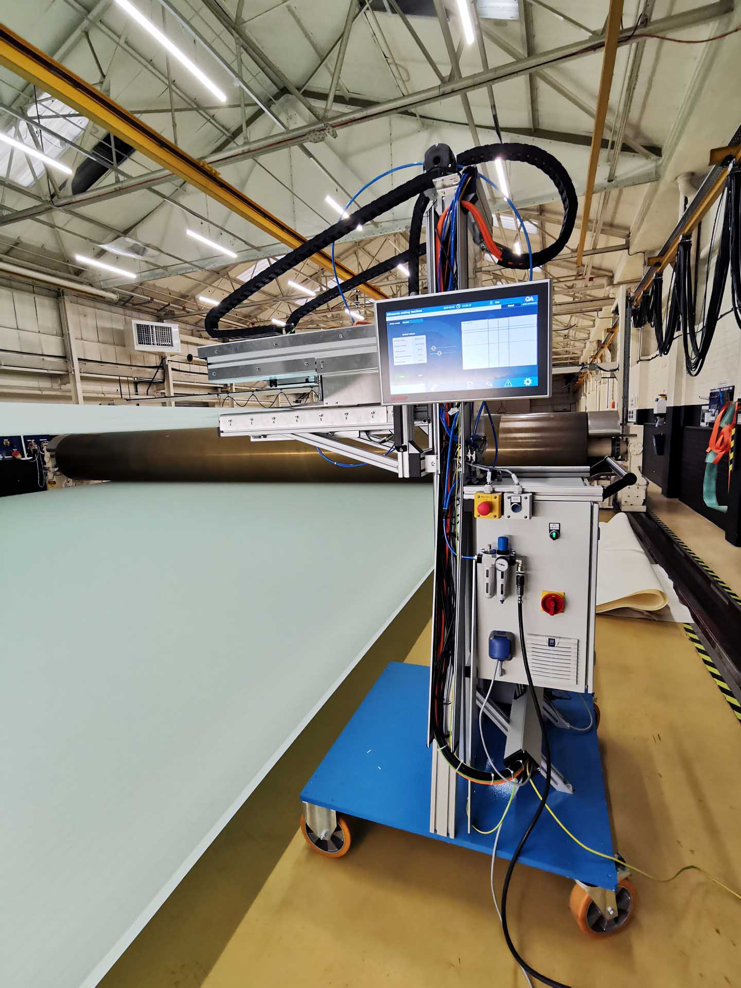
Machines for the production of paper are divided into several sections, each requiring a special conveyor belts the so-called paper machine clothing. These are belts, some of which are several meters wide and made of high-tech textiles with different properties. The paper pulp is transported through the paper machine on them. Due to different machine types and paper formats, these clothings, which are made of high-tech textiles, are supplied in customer-specific formats. However, on the weaving machines used to produce the clothings the width can only be roughly adjusted. Therefore, after production, a cutting process is required to cut the fabric to the desired width. For this cutting process, new mobile cutting machines were developed and put into operation in cooperation with Hille Engineering for a producer of paper machine clothing.
For the cutting process, the clothing is stretched with the help of two calenders. The cutting machines are positioned and aligned on both sides of the clothing. The calenders now move the clothing through the machine until the belt has run through once completely. The textile is clamped in the machine between an ultrasonic head and a cutting wheel. The ultrasonic excitation causes the material to be cut and the edge is slightly melted by the heat generated simultaneously. This seals the edge and prevents it from fraying.
When moving the very large-format coverings, there are always slight changes in position orthogonal to the direction of movement. To compensate for these movements and ensure a consistent width of the clothing, both cutting machines must follow these changes. For this purpose, each of the machines is equipped with a vision system.
The ultrasonic head and camera are mounted on two independently moving axes. Colored threads which are inserted into the fabric at regular intervals in the direction of movement makea changes in their position detectable by the camera. The deviation from the target position is transmitted to the cutting axis so that an adjustment can be made.
Hille Engineering was responsible for the mechanical design and manufacturing in this project. The control, drive technology and image processing of the cutting systems were implemented by Quality Automation completely with components from Beckhoff. PLC and Motion Control have long been part of the Beckhoff product portfolio, but with TwinCAT Vision the option of image processing is now also integrated on a uniform control platform. This not only simplifies the configuration of the system, but also enables camera-based control and synchronization in real time. In this way, the position data acquired by the camera on the machine is processed by the motion control in the same PLC cycle and the position of the axes is adjusted without latency. The comprehensive library also enables the solution of complex requirements in the area of geometry control or surface analysis. All cameras with ‑GigE–Vision interface can be connected to the controller. Only the appropriate driver must be installed on the Beckhoff Industrial PC. A camera and optics from Matrix Vision, both in dust- and vibration-proof design, are used on the machines.
User interface with camera image, Components in the switch cabinet
This type of image processing integration has the advantage that both the camera image and the machine parameters and settings can be seen on a common panel and no separate monitor needs to be attached to the machine for image display. The space required in the control cabinet is also significantly reduced by this integration, enabling the construction of small and lightweight systems.
The visualization was implemented using a client-server solution and a Beckhoff panel. The generous format of the screen and the high resolution enable convenient operation and display of parameters and recorded images that can be recognized even from a distance. The HMI server provides the user interface by means of a modular web server. Via a browser, the user interface can be called up not only on the panel, but also on a mobile end device or PC. For this, the PLC and the end device must be in the same network. This is possible by integrating the equipment into the company network or establishing a local network. Especially with regard to the large distance between the two cutting machines, this is very helpful for operating and monitoring both machines at the same time.
The entire system architecture can be transferred to numerous other plant and machine concepts due to the scalability and the large functional scope of TwinCAT 3. In particular, if a connection to databases or integration of diverse hardware in the area of drive technology, sensor technology or image processing is planned, a concept with components from Beckhoff is always worth considering.
You are currently viewing a placeholder content from YouTube. To access the actual content, click the button below. Please note that doing so will share data with third-party providers.
More Information
