As part of his bachelor’s thesis, Aaron Laufs is developing a control system for winding systems based on a model with dancer and tractive force controls.
Motivation and background
In a past bachelor thesis we designed and implemented a model of a winding line with PLC-based control. The existing test model is now to be modified and equipped with software and hardware from Mitsubishi. “Together with Mitsubishi, I will develop a control basis for winding applications, which can then be used flexibly in the future for different motor and system sizes,” says Aaron.
Aaron Laufs is currently a student at Aachen University of Applied Sciences in the field of automation and drive technology. After leaving school, he first trained as an electronics technician for industrial engineering and, while still in training, earned his technical baccalaureate at night school. With his apprenticeship and some work experience, Aaron decided to study full-time, which has now led him to QA since the beginning of this year. He finished his internship successfully and we are pleased that Aaron would like to complete the upcoming bachelor thesis with us.
The test setup
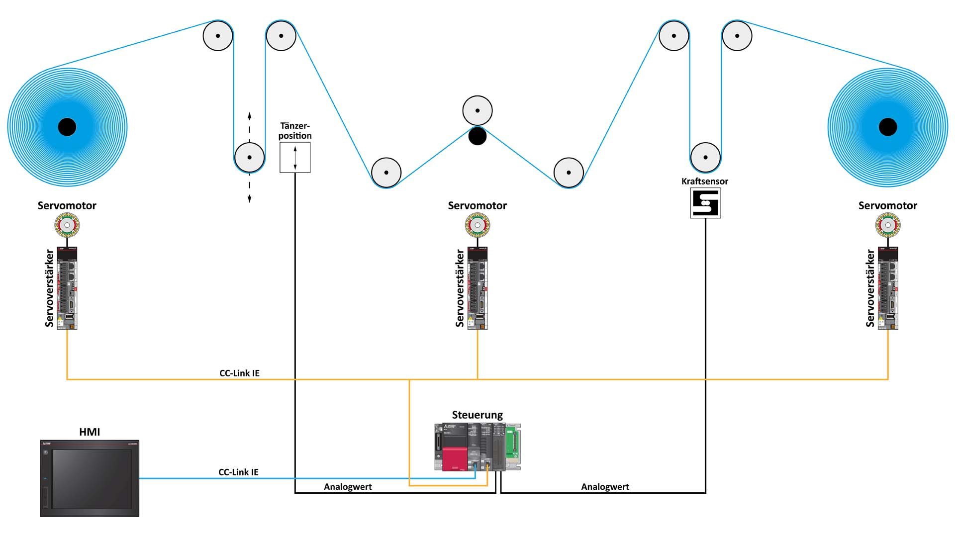
The Fischertechnik model simulates almost real conditions. A feed unit in the middle between the two winding units sets the speed. On the left side, a dancer control is implemented. In this process, the material is guided behind the winder via a vertically freely movable dancer. If possible, the dancer should always remain in a central position, and the control system reacts to deviations from this position. The path is measured by a sliding potentiometer. For the second method, tension control, a fixed deflection pulley is used, with force sensors attached to its foundation. Here, the tension on the pulley is used as the controlled variable.
Content and outlook
In the coming months, Aaron will develop the control base step by step using Mitsubishi components. After familiarization with the hardware, the winding application and the control loop, the controlled variables must be determined and the control loop implemented. For this purpose, modules are created with the GX Works 3 software, which perform physical calculations. Subsequently, the entire control loop is simulated in the software and initial tests are carried out. After that, the model is converted. For this purpose, our premium system partner Mitsubishi provides us with, among other things, the RD78G4 motion controller, a J5 series servo amplifier and the HK-KT12W servo motor. The software will run on a MELSEC iQ‑R series controller.
We are looking forward to this exciting and innovative bachelor thesis and wish Aaron much success in the coming months.